Alarm groups output settings

Overview

This page is used to configure outputs from the Digital Output (DO) Board based on the status of Alarm Groups. The settings defined on this page determine how the DO board responds to changes in alarm group conditions.

Prerequisites

Before proceeding, ensure the following requirements are met.

  • FCU/FU configuration and the corresponding I/O board configuration have been completed.

  • Alarm Group settings have been completed in Channel Settings.

Procedure - Alarm groups output settings

1. Alarm group selection

Click "Set Address" for the alarm group to which output settings will be applied.
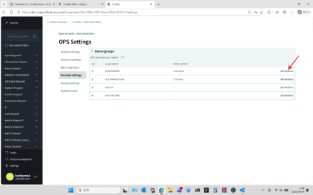
click on set address

2. Output type selection

Select an output type from the Output type drop-down list.
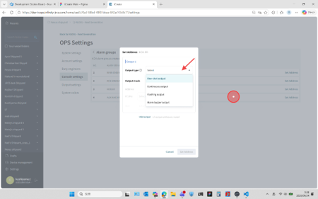
select output type

Output type

Type

Description

One-shot output

When a new alarm is generated in the selected alarm group, a pulse signal is output. The pulse width can be configured using "Signal Width".

Continuous output

Output remains ON as long as an alarm condition exists within the alarm group. When the all alarms in the selected alarm group have been cleared, the output turns OFF.

Flashing output

When a new alarm is generated in the selected alarm group, the output blinks. When the alarm buzzer is silenced, the output changes from blinking to steady ON. When the all alarms in the selected alarm group have been cleared, the output turns OFF.

Alarm buzzer output

When a new alarm is generated in the selected alarm group, the output turns ON. When the alarm buzzer is silenced, the output turns OFF.

3. Output mode selection

Select an output mode from the Output Mode drop-down list.
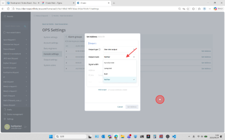
select output mode

Output mode

Mode

Description

Function test

Work in Function Test Mode.

Lamp test

Work in Lamp Test Mode.

Both

Work in both Function Test and Lamp Test Modes.

Neither

Work in neither Function Test nor Lamp Test Modes.

4. Signal width for one-shot output (optional)

Enter the signal pulse width. This setting is available only when Output Type is set to "One-Shot Output".
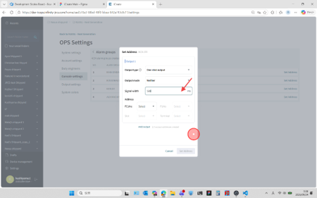
input signal width

Enter a value between 200 ms and 2000 ms

5. DO board slot selection

Select the I/O board to which the DO settings will be applied. Select the FCU No., FU No., and Slot No. from the corresponding drop-down lists.
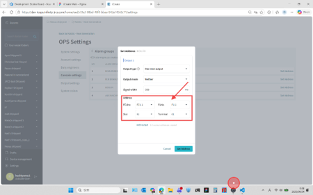
select output location

To select an I/O board installed in an FCU, choose "No Selection" from the FU No. drop-down list.

6. Output setting addition (optional)

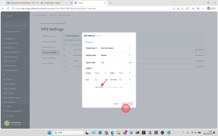
Click "Add Output" if you want to add more output setting for the selected alarm group.

click on add output

7. Added output setting confirmation

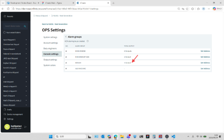
The list displays the number of output settings configured for each alarm group.

confirm added setting